Appendix B: Constant level tank design
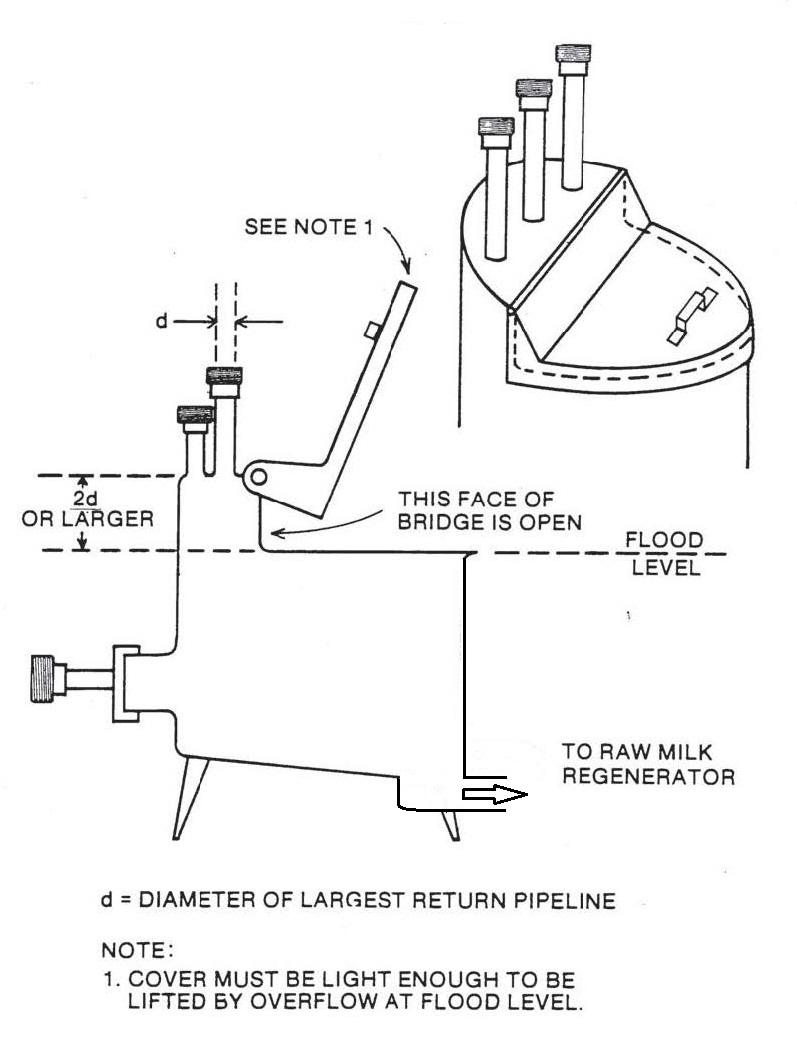
Figure 1 – Constant level tank overview

Description of image – Constant level tank overview
This image shows an overview of a constant level tank. The face of bridge is open. The cover on the tank is light enough that if the milk reaches the flood level, the cover will be lifted. The air break above the flood level is at least two times the diameter of the largest return pipeline above the maximum overflow point of the constant level tank. Raw milk outlet is at a level below the bottom of the tank.
Figure 2 – Constant level tank with elevated bridge and vent

Description of image – Constant level tank with elevated bridge and vent
This image shows a constant level tank with an elevated bridge with vent. The bridge is enclosed and the cover is at least two times the diameter of the largest raw product supply pipeline. The cover of the constant level tank is light enough that if the milk reaches the flood level, the cover will be lifted. The air break above the flood level is at least two times the diameter of the largest return pipeline above the maximum overflow point of the constant level tank. The size of the vent pipe is the size of the largest return pipeline or larger. Raw milk outlet is at a level below the bottom of the tank.
Figure 3 – Side overflow (elbow)

Description of image – Side overflow (elbow)
This image shows a constant level tank with the side overflow (elbow). The elbow diameter is at least two times the diameter of the largest raw product supply pipeline. The air break above the flood level is at least two times the diameter of the largest return pipeline above the maximum overflow point of the constant level tank. The size of the vent pipe is the size of the largest return pipeline or larger. Raw milk outlet is at a level below the bottom of the tank.
Figure 4 – Internal overflow

Description of image – Internal overflow
This image shows a constant level tank with an internal overflow. The internal overflow tube is at least two times the diameter of the largest raw product supply pipeline. If the largest dimension of the tank is less than 3 feet, the overflow tube ends at least one diameter of the largest raw product supply pipeline but no less than 4 inches above the floor. If the largest dimension of the tank is greater than 3 feet, the overflow tube ends at least one diameter of the largest raw product supply pipeline but no less than 6 inches above the floor. The air break above the flood level is at least two times the diameter of the largest return pipeline above the maximum overflow point of the constant level tank. The size of the vent pipe is the size of the largest return pipeline or larger. Raw milk outlet is at a level below the bottom of the tank.
- Date modified: