
Appendix D: Criteria for the evaluation of computerized food safety controls
On this page
Definitions
For the purposes of this document, the following definitions apply
- Address
- A numerical label on each input or output of the computer. The computer uses this address when communicating with the input or output.
- Computer
- A very large number of on-off switches arranged in a manner to sequentially perform logical and numerical functions.
- Default mode
- The pre-described position of some memory locations during start-up and standby operations.
- Electrically alterable programmable, read only memory (EAPROM)
- An electrically alterable programmable, read only memory. Individual memory locations may be altered without erasing the remaining memory.
- Electrically erasable programmable, read only memory (EEPROM)
- An electrically erasable programmable, read only memory. The entire memory is erased with one electrical signal.
- Erasable, programmable, read-only memory (EPROM)
- An erasable, programmable, read-only memory. The entire memory is erased by exposure to ultra-violet light.
- Fail Safe
- Design considerations that cause the instrument or system to move to the safe position upon failure of electricity, air, or other support systems.
- Field alterable
- A device having a specific design or function that is readily changed by user and/or maintenance personnel.
- Force off
- A programmable computer instruction that places any input or output in the "off" state, independently of any other program instructions.
- Force on
- A programmable computer instruction that places any input or output in the "on" state, independently of any other program instructions.
- Input
- A data set applied to the input bus of the computer that is used by the computer to make logical decisions and whether or not to activate one or more outputs. Input consists of data from temperature and pressure instruments, liquid level controls, tachometers, microswitches, and operator-controlled panel switches.
- Input/output bus
- An electrical connection panel that provides for the connection of all inputs and outputs to the computer. The input/output address labels are found on this panel. Indicator lights showing the status (on/off) of all inputs and outputs are usually available on this panel.
- Last state switch
- A manually operated switch located on the input/output bus that instructs the computer to place all outputs in the "on", "off" or "last state" during a start up. The "last state" position instructs the computer to place the outputs in whatever state (on or off) occurred during the last loss of power.
- Operator override switch
- A manually operated switch located on the input/output bus that permits the operator to place any input or output in the on or off position, independently of any program instructions.
- Output
- Electrical signals from the computer that turn on or off valves, motors, lights, horns, and other devices being controlled by the computer. Outputs may also consist of messages and data to the operator.
- Programmable controller
- A computer, with only limited mathematical ability, that is used to control industrial machines, instruments and processes. Most computers used on high-temperature short-time (HTST) pasteurizers will be programmable controllers.
- Random access memory (RAM)
- A memory used by the computer to run programs, store data, read input and control outputs. The computer may either read the memory or write data into the memory.
- Read-only memory (ROM)
- A memory used by the computer to run its own internal unchangeable programs. The computer may only read from the memory; it cannot write into the memory or alter the memory in any way.
- Standby status
- The computer is turned on, running, and waiting for instructions to start processing input data. This instruction is usually accomplished by a manually operated switch.
- Status printing
- Some computers are programmed to interrupt printing of the chart record print the status of key set points and conditions such as cold milk temperature, holding tube temperature, diversion temperature setting and chart speed.
Criteria
The following criteria applies to computers or programmable controllers when applied to High temperature short time (HTST), Higher heat shorter time (HHST) and ultra-high temperature (UHT) pasteurization systems used for milk and milk products.
- Dedicate the computer or programmable controller to food safety control of the pasteurizer.
- do not use it for any other assignments involving the routine operation of the facility
- do not put the food safety computer under the command or control of any other computer system. For example:
- it does not have an address that is addressable by any other computer system
- a host computer cannot override its commands or place it on standby status
- all output addresses of the food safety computer are ready to process data at any time
- Use a separate food safety computer on each pasteurizing system.
- Provide the status of the input/output bus of the public health computer as inputs only, to other computer systems. Provide the wiring connections with isolation protection such as solenoid relays, diodes, or optical-coupling devices to prevent the public health input/output bus from being driven by the other computer system.
- Ensure all food safety controls assume the fail-safe (divert) position in the following situations:
- on loss of power to the computer
- when the computer is in standby status
- when the computer is in default mode, such as when internal diagnostic checks are being performed automatically during start-up
- Some computers or programmable controllers have input/output buses with “last state switches" that permit the pasteurizer operator to decide what state the output bus will take on power-up after a shutdown or loss of power. The choices are on, off, or "last state" occurring when the computer lost power. Place these "last state switches" in the fail-safe position.
- Write the computer program so that the computer monitors all inputs, and updates all outputs on a precise schedule (at least once every second). Most computers will be capable of performing this function many times in 1 second.
- Store computer programs in some form of read-only memory that is available when the computer is turned on. Do not use tapes or disks.
- Seal the access to the computer program, including any telephone modem accesses. If the Input/output bus contains "last state switches", seal the Input/output bus. Use test procedures and instructions provided by the vendor to confirm that the correct program is in use during a start-up, and whenever the seal is broken.
- If the computer contains force-on and force-off functions, provide the computer with indicator lights showing the status of the force-on and force-off function. Clear all force-on and force-off functions before sealing the computer.
- Do not install operator override switches on the input/output buses of the food safety computer.
- Computerized systems that provide for printing the recording chart:
- maintain proper calibration during chart printing
- ensure the computer is not diverted from its food safety tasks for more than 1 second
- upon returning to food safety control, ensure the computer completes at least 1 full cycle of its food safety tasks before returning to chart printing
- When printing a chart, some systems provide status reports on the chart paper of selected input/output conditions. This is usually done by interrupting the printing of the chart and printing the input/output conditions.
- ensure these interrupts do not prevent a continuous record from being recorded on the chart
- when an interrupt is started, print the time of the start of the interrupt on the chart at the beginning of the interrupt and at the end of the interrupt
- ensure the time interval during which the computer is diverted from its food safety control tasks for status printing does not exceed 1 second
- upon returning to food safety control, ensure the computer completes at least 1 full cycle of its food safety tasks before returning to status printing
- When the computer prints the holding tube trace at specific intervals, rather than a continuously changing line, print the temperature readings not less than once every 5 seconds. In addition, during the thermometric response test, print the temperature or indicate fast enough to accurately measure the 7°C (12°F) rise in temperature as described in Test 7 of Critical process test procedures.
- When the computer prints the frequency pen position (the position of the flow diversion device (FDD), forward or divert) at specific intervals, rather than continuously, ensure the computer can recognize all changes of position and print them on the chart. In addition, ensure the frequency pen position and temperature in the holding tube is printed on the chart in a manner that the temperature in the holding tube can be determined at the moment of a change of position of the FDD.
- Have a built-in program for test procedures or a protocol available so that all applicable tests outlined in Critical process test procedures for the following instruments can be performed.
- Recording thermometers
- temperature accuracy
- time accuracy
- check against indicating thermometer
- thermometric response
- Flow diversion devices
- valve seat leakage
- operation of valve stem(s)
- device assembly
- manual diversion
- response time
- time delay intervals, if used
- Booster pumps
- proper wiring
- proper pressure control settings
- Flow promoting devices (timing pumps)
- holding time in holder
- proper wiring interlocks
- Recording thermometers
- Computers require high quality (clean) and well regulated power supplies to operate reliably and safely. Spurious voltage spikes can cause unwanted changes in computer RAM. Some mechanical and electrical components also deteriorate with age. The following solutions help to prevent these unwanted changes in computer RAM:
- have 2 permanent programs in the computer; 1 in RAM and 1 in ROM
- through a self-diagnostic test, these 2 programs can be compared routinely
- if there are differences in the programs, the computer would go into default mode
- download the program from ROMto RAM at every start-up
- have the computer read program directly from ROM that is unchangeable
- this approach is practical only in large volume applications such as microwave ovens
- for most small volume applications, the read-only memories are field alterable, such as EPROM, EEPROM and EAPROM
- these cannot be relied upon to maintain a permanent record
- ensure that the proper program is in computer memory before sealing the computer
- have 2 permanent programs in the computer; 1 in RAM and 1 in ROM
- Use the logic diagrams in the Computerized systems logic diagrams section to develop the computer programs used for food safety controls on pasteurizers. Minor modifications to these diagrams can be made to accommodate or delete items that are unique to a specific HTST or HHST pasteurizer system, such as magnetic flow meters used as replacement for timing pump, the flush cycle on the detect stem of the FDD, and the 10 minute delay of the booster pump and FDD that permits the timing pump to run during cleaning operations. Have available a protocol that can be followed to demonstrate that the program performs as designed under actual production conditions. An example is provided under the Test procedure section.
- The logic diagrams for the FDD and booster pump show a programmed clean-in-place (CIP) operation as part of the computerized system. Where a different computer is used for CIP operations (so that CIP programs may be changed by plant personnel), provide the connections between the FDD, booster pump and plant computer with solenoid relays or similar devices on the outputs to the FDD and booster pump. This prevents them from being operated by the computer used for CIP, except when the mode switch of the FDD is in the "CIP" position.
Test procedure
The following is 1 method of confirming proper operation of all required food safety controls.
- Identify all system components which are micro-processor controlled for CIP.
- Locate and identify outputs for the above.
- With the inspect-process-CIP selector switch at CIP, and after 10 minutes time delay, manually force on each output and confirm the operation of the controlled component.
- With the inspect-process-CIP selector switch at Process, again force on the above defined outputs. The booster pump, FDD and devices interlocked with these components do not operate. And, with the flow control device (FCD) (timing pump) off, those components that are interlocked with the FCD (timing pump) do not operate.
Computerized systems logic diagrams
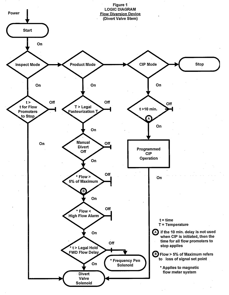
Description of flowchart - Logic diagram of a flow diversion device (divert valve stem)
This image shows a logic diagram of a flow diversion device (divert valve stem) for a computer or programmable logic controller (PLC).
- From the start position, if power is "On", the program can go into Inspect, Product, or CIP mode.
- In inspect mode, if the time is greater than the time required for the flow promoters to stop, a signal is sent to the divert valve solenoid.
- In product mode, the following conditions must be met for the system to remain in forward flow:
- the temperature must be greater than pasteurization temperature
- the manual divert must be off
In addition, if the system is a magnetic flow meter system:
- The flow must be greater than 5% of the maximum (this refers to a loss of signal set point).
- The flow must be less than the high flow alarm.
- The time must be greater than the legal hold forward flow delay.
If any of these conditions are not met, the divert valve solenoid is signalled to divert the flow.
A frequency pen solenoid records whether the product is in forward or divert flow.
- In CIP mode, after a delay of greater than 10 minutes, or the time necessary for all flow promoters to stop (if they cannot operate), CIP programming begins to clean the system. The divert valve solenoid allows the valve to move for cleaning.
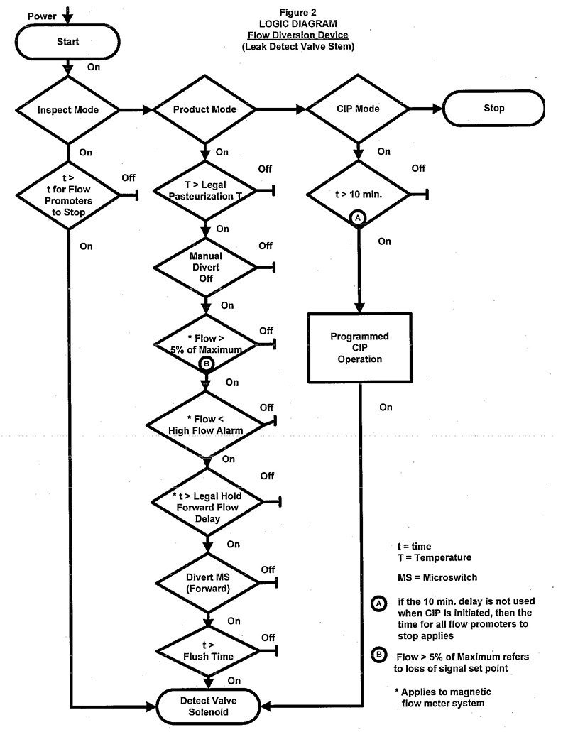
Description of flowchart - Logic diagram of a flow diversion device (leak detect valve stem)
This image is a logic diagram of a flow diversion device (leak detect valve stem) for a computer or programmable logic controller (PLC).
- From the start position, if power is "On", the program can go into Inspect, Product, or CIP mode.
- In Inspect mode, if the time is greater than the time required for the flow promoters to stop, a signal is sent to the detect valve solenoid.
- In Product mode, the following conditions must be met for the system to go into and remain in forward flow:
- the temperature must be greater than pasteurization temperature
- the manual divert must be off
For the magnetic flow meter system:
- The flow must be greater than 5% of the maximum (this refers to a loss of signal set point).
- The flow must be less than the high flow alarm.
- The time must be greater than the legal hold forward flow delay.
As well:
- The divert microswitch must be in forward position.
- The time must be greater than the flush time.
If any of these conditions are not met, the detect valve solenoid is signalled to divert the flow.
- In CIP mode, after a delay of greater than 10 minutes, or the time necessary for all flow promoters to stop (if they cannot operate), CIP programming begins to clean the system.
- the detect valve solenoid allows the valve to move for cleaning
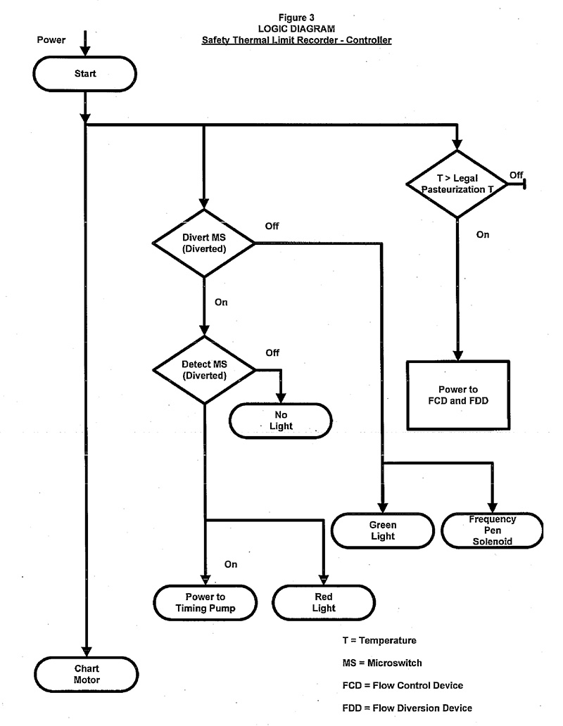
Description of flowchart - Logic diagram of a safety thermal limit recorder-controller
This image is a logic diagram of a safety thermal limit recorder-controller for a computer or programmable logic controller.
- When the program starts the chart motor is activated.
- If the divert microswitch is on and the divert flow is detected by the detect microswitch, a red light appears and the timing pump is powered.
- if the divert flow is not detected by the detect microswitch, no light appears
- if the legal pasteurization temperature is met the, power goes to the FCD and the FDD
- the microswitch is in forward flow mode, a green light appears and the frequency pen solenoid is activated to record forward flow
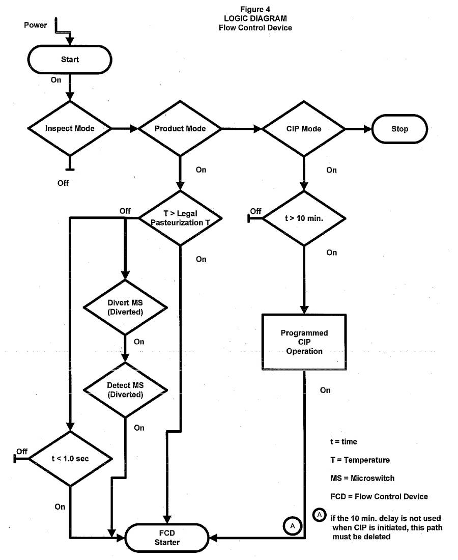
Description of flowchart - Logic of a diagram flow control device
This image is a logic diagram of a flow control device for a computer or programmable logic controller.
- In Inspect mode, the FCD is off.
- In Product mode:
- if the temperature is greater than legal pasteurization temperature, a signal goes to the FCD starter to operate
- if the temperature is not met, a signal is sent by the divert microswitch and the detect microswitch which signal the fully diverted flow position
- the FCD starter is then energized
- when the pasteurization temperature goes below the legal pasteurization temperature a time delay relay may be installed to permit the FCD to continue operating during the normal time it takes for the FCD to move from forward flow to diverted flow (not more than 1 second delay)
- In CIP, there is a 10 minute delay before the CIP operation starts and a signal is sent to the FCD starter. If the 10 minute delay is not used when CIP is initiated then no signal can be sent to the FCD starter.
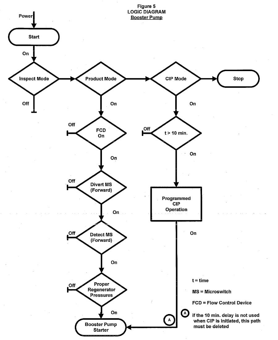
Description of flowchart - Logic diagram of a booster pump
This image is a logic diagram of a booster pump for a computer or programmable logic controller.
In Inspect mode, the booster pump starter is off.
In Product mode, the following conditions must be met before a signal is sent to the booster pump:
- flow control device is on
- the divert microswitch is in the forward position
- the detect microswitch detects the forward flow
- adequate pressure in the regenerator is reached
In CIP mode, after a delay of 10 minutes or more, scheduled CIP operation starts. If the 10 minute delay is not used, then the booster pump starter cannot be operated during CIP.
- Date modified: